LANTIME M600/MRS:
NTP Time Server synchronized by GPS/1PPS/10MHz/IRIG/NTP
Key Features:
- Synchronization of NTP and SNTP compatible clients
- Web based status and configuration interface and console based graphical configuration utility
- Alert-Notification system of status changes by e-mail, WinMail, SNMP or on external wall mount displays
- Full SNMP V1,V2c,V3 support with own SNMP-daemon for status/configuration and SNMP traps
- USB port for performing updates, locking front panel buttons and backup/restore of configuration and log files.
- Four independent RJ-45 Ethernet interfaces 10/100 MBit
Intelligent Switching between available Synchronization Sources:
- GPS or GNSS (GPS, GLONASS, Galileo, BeiDou)
- Time Code (e.g. IRIG-B), both DCLS and AM
- Pulse Per Second (PPS)
- 10MHz (TTL)
- External NTP Servers
The LANTIME M600/MRS (Multi Reference Source) NTP Time Server uses an internal ultra stable oscillator as its stratum 0 reference. The oscillator can be disciplined based on other NTP servers over a network connection or – after connecting an (optional) GPS antenna - by GPS. In isolated networks without any possibility of using an external NTP server or a GPS antenna, the MRS utilizes its OCXO HQ to maintain a stable time base after the time has been manually set during initial configuration (free running mode).
The LANTIME M600/MRS is a reliable and accurate time source for all NTP- or SNTP-compatible client systems and uses a built-in ultra-stable oscillator as its primary time reference and it is designed to provide a reliable time source for network environments where more than one reference is available. This oscillator can be disciplined by other NTP time servers over the network, a PPS (Pulse Per Second) signal, a 10MHz Frequency or IRIG time codes generated by external devices. If required, a GPS antenna (optional accessory) can be connected as an additional source of time, allowing the MRS to switch between the available reference signals.
Additionally, the LANTIME M600/MRS can be run in a fully independent mode in networks where no external source of time is available. This requires setting the time manually during initial configuration. The battery buffered RTC keeps the time during power outages or reboots and the integrated oscillator maintains a stable timebase during normal operation.
All outputs of the M600, including PPS, 10MHz and the Sysplex Timer output are fully functional and stable, no matter which reference is used as a synchronization source. The „automatic" mode of the MRS will use GPS as its primary synchronization source and switches to the NTP reference mode whenever GPS reception is not possible.
The integrated OCXO-HQ guarantees a stable time base, a free running MRS (without any external reference like GPS or NTP) shows a maximum time error of +/- 788 ms per year.
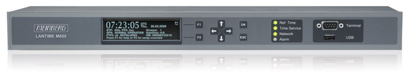
A large VF display shows the state of the internal GPS receiver and the NTP subsystem. Three LEDs (green/red) indicate the status of the three main components: Reference Time, Time Synchronization Service (NTP) and Network (Link status). A fourth red LED is labeled ALARM and can be configured to signal any event that is covered by the notification handling routines.
Configuration of the system can be performed by using a standard web browser to access the extensive but straightforward web interface. Alternatively a text based and menu driven setup utility can be started from the shell prompt after logging into the unit via Serial Console, Telnet or SSH.
Front Panel:
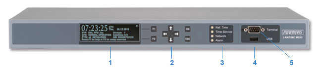
- Graphical VF display (256 x 64 dots)
-
Buttons:
F1: show help and additional informations
F2: overview of network parameters
4 arrow buttons: select next menu and change value of parameters
OK button: save changes or enter submenu
ESC button: cancel menu and one level up -
LEDs:(front panel interface)
3 x Bicolor LEDs:
- Ref. time (e.g. GPS)
- Time Synchronization
- Service (NTP) and Network-Link status
1 x Red alarm LED (configurable) -
1 x USB (Rev. 1.1) front panel interface to:
- install firmware upgrades
- backup and restore configuration files
- copy security keys
- 1 x RS232 front panel interface, 9pin D-Sub male connector for initial setup and configuration
Rear Panel:
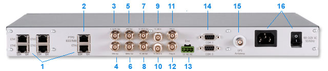
- LAN interface, RJ45 connector, status LEDs for link, activity, speed (10/100 MBit)
- Frequency Synthesizer, from 0.1 Hz up to 10 Mhz, TTL into 50 ohm, female BNC connector
- Pulse Per Minute (PPM), TTL into 50 ohm, pulse duration 200 msec, active high, female BNC connector
- Pulse Per Second (PPS) input, TTL, pulse duration >= 5µs, active high, female BNC connector
- 10 MHz, TTL input, female BNC connector
- IRIG-B pulse-width modulated DC output (DCLS), TTL into 50 ohm, active high, female BNC connector
- IRIG-B amplitude modulated (AM) sinewave output, peak-to-peak voltage: 3 V into 50 ohm, female BNC connector
- Time Code AM (modulated) input, BNC connector, isolated by transformer
- Time Code DCLS (unmodulated) input, BNC connector, isolated by opto-coupler
- Pulse Per Second (PPS), TTL into 50 ohm, pulse duration 200 msec, active high, female BNC connector
- Reference Frequency 10 MHz, TTL into 50 ohm, female BNC connector
- Alarm relay output, change-over contact, 3pin DFK connector
- RS232 interface, 9pin D-Sub female connector
- Meinberg GPS antenna input, BNC connector, isolated
- Power Supply Unit (85-264V AC) - Power consumption: 25W